Signal Flow Graph
Signal flow
graph is the graphical representation of control system in which nodes
representing each of system variables are connected through the direct
branches. It may be regarded as the simplified version of Block Diagram. It
applies only to linear system.
Basic Terminology of Signal Flow Graph
Branch :- Nodes are connected by line
segments called branches, these branches have associated branch gain and
direction, direction is represented by arrow. A signal can transmit through the
branch only in the direction of arrow.
Input Node / Source node :- It is a
node having outgoing branches only.
Output Node / Sink Node :- It is the
node having only incoming branches.
Note :- In a signal flow graph output can
be defined from any other node by extending the it with a gain of unity.
Mixed / Chain Node :- It is a
node having both incoming and outgoing branches.
Path :- It is the traversal of connected
branches in the direction of branch arrow such that no node is traversed more
than once. A signal flow graph can have one or more than one paths.
Forward Path :- It is a path starts from
input node and end at an output node.
Loop :- It is a path which originates and
terminates at the same node.
Non Touching Loop :- Two or more
loops are said to be non-touching if they do not have a common node.
Mason Gain Formula
Transfer
Function = nƩk=1 Pk .Δk / Δ
Where,
n = number of forward paths
Pk = Path gain of the
forward Kth path
Δ = 1 – {Sum of loop gains all
individual loops} + {Sum of gain of product of two non-touching loops} – {Sum
of gain products of three non-touching loop}...........
ΔK
= It is that value of “Δ” obtained by removing all the nodes touching Kth
forward path.
Calculation of transfer function by using Mason Gain formula
Let us take an example
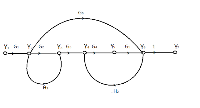
In this Signal Flow Graph,
There are seven nodes these are Y1,
Y2, Y3, Y4, Y5, Y6, Y7.
In which Y1 is input node or source node and Y7 is output
node or sink node and rest of nodes are mixed or chain nodes.
These seven are connected through the
branches having forward transfer gain G1, G2, G3,
G4, G5, 1 respectively and Y2, Y6
is connected through another branch have forward transfer gain G6.
Similarly Y2 and Y3 is
connected through a branch having negative gain H1 and Y4
and Y6 is also connected through a branch having negative gain H2.
So according to formula first we have
to find the number of forward path and product of the gains of those forward
paths.
There are two forward paths
P1 = G1G2G3G4G51
P2 = G1G61
Then, we have to find product of gain
of individual loops. So there are two individual loops these are
L1 = -G2H1
L2 = -G4G5H2
Then we have to find product of gain
of two non-touching loop. There are two non-touching loop these are
L1 = -G2H1
L2 = -G4G5H2
Product of gain of these two loops is
I1 = G2G4G5H1H2
Then we have to find Δk.
Δ1 =1
Δ2 = 1
So put all those value in Mason Gain
formula after putting these values we get
So In this way we apply the Mason Gain formula for a particular problem.
How to convert Block Diagram into Signal Flow Graph
There are some steps which we have to
follow for the conversion of Block Diagram into Signal Flow Graph
Step :- 1 Convert all the variables, summing point,
take-off point, junctions into nodes
Step :- 2 Represent all the blocks of the block
diagram as branches with given directions.
Step :- 3 The transfer function of the particular
block represent the gain of the corresponding branch of that particular block.
Step :- 4 Connect all the nodes with
branches according to the block diagram convention and direction.
Let us take an example
 |
| Block diagram of feedback control system. |
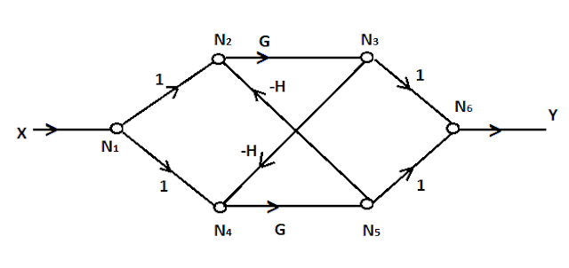
In the above diagram there are three
summing points S1 S2 and S3 respectively, two
take-off points T1 and T2 and one junction point J1.
So, according to above steps convert
S1 ――> N2
S2 ――> N4
S3 ――> N6
T1 ――> N3
T2 ――> N5
J1 ――> N1
Connects all the nodes with their
respective branches and assign the gain for all the branches accordingly.


No comments:
Post a Comment
Please feel free to provide feedback and suggestions, and also don't hesitate to ask your questions.