A chopper is a static circuit that converts fixed DC input
voltage to a variable dc output voltage. Normally output voltage of chopper is unregulated.
Dc Converters can be used as switching mode regulators to convert dc voltage, normally unregulated voltage to a regulated dc output voltage. By using Pulse Width Modulation (PWM) this regulation is achieved.
The three basic types of dc converters which are using
switching mode regulators are
- Buck Converter
- Boost Converter
- Buck Boost Converter
Boost Converter
As the name implies Boost converter is a dc – dc converter
using switch mode regulator to step up the voltage while step down output current.
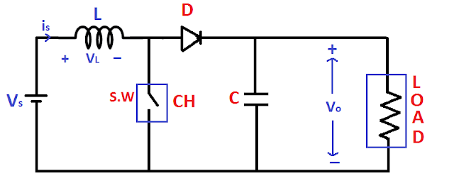
Boost Converter Circuit Diagram
In the above figure, we have seen that inductor is connected
in series with input source this leads to source current be constant. And
Capacitor is connected parallel to load this leads to constant voltage across
the load.
Boost converter working
Let us say that switching frequency of switch is F and correspondingly time period is T = 1/F.
Let us say that switch is on for Ton
time and off for Toff time.
So total time period
T = Ton + Toff
Duty Ratio (D):-
It is the ratio of on time to total time period.
So according to above discussion we can divide the circuit operation in two mode.
- Mode- I, when switch is on, during Ton time period
- Mode – II when switch is off, during Toff time period
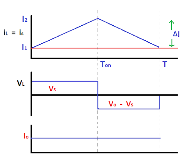
When the switch is on the current path is shown in the given
figure. During this time period, inductor stores energy and voltage across the
inductor is equal to the source voltage.
VS = VL
ΔI = Peak to Peak ripple current
When the switch is off the current path is shown in the given
figure. During this time, inductor discharge energy through the diode. But
inductor current cannot go down instantaneously this current is forced to flow through
the diode, capacitor and load until the switch is on for next cycle. As
inductor discharge the polarity of the inductor voltage becomes reversed.
During next cycle when the switch is on, inductor current changes from I1 to I2.
After applying KVL in the given circuit you will get
Vo = Vs
+ VL
VL = Vo -
Vs
Consider the circuit is lossless, so that the energy stores
in the inductor during on time and energy releases the inductor during off time
is equal.
So
Vs.Ton - (Vo-Vs). Toff
= 0
Vs.T = Vo.Toff
As we assume circuit is lossless so that input power is equal to output power.
Pin = Po
Vs.Is = Vo.Io
Boost Converter Design using MATLAB Simulink
2. Select the following components from MATLAB library.
Dc voltage
source :-> Go to Library
>> Simscape >> Electrical >> Specialized Power System
>> Sources >> Select Dc Voltage Source.
MOSFET (any
switch) and Diode
:-> Go to Library >> Simscape
>> Electrical >> Specialized Power System >> Power
Electronics >> Select MOSFET and Diode
Three RLC
branches Modified accordingly as per circuit diagram
Go to Library >> Simscape >> Electrical >>
Specialized Power System >> Passives >> Select Series RLC Branch
Note
- Don’t select series RLC Load.
- By double click on each RLC branch select resistance, capacitance and inductance.
Current Measurement
and Voltage Measurement
Go to Library >> Simscape >> Electrical >>
Specialized Power System >> Select Two Voltage Measurement and Current
Measurement.
Pulse
Generator :-> Go to Library >> Simulink >> Sources
>> Select Pulse Generator.
Scope :-> Go
to Library >> Simulink >> Sinks >> Select Two Scopes
Powergui
block :-> Go to Library >> Simscape >> Electrical
>> Specialized Power System >> Select Powergui Block.
Display :-> Go
to Library >> Simulink >> Sinks >> Select Display. To display
your values
3. Connect this block according to the circuit diagram.
4. Assign values for different components as per requirements by
double clicking on them.
5. Select stop time 0.2 Sec. and then run your Simulink model.
Some important questions from internet
1) 5V to 10V DC-DC Converter
In this converter desired output voltage Vo is 10V
and supply voltage Vs is 5V. So from Above discussion we can say
that equation 2 will help to get this desired value.
Vo = Vs / (1 - D)
10V = 5 / (1 - D)
From above discussion we can say that by making duty ratio
0.5 we will get 10V output from 5V supply voltage.
For given values, values of inductance and capacitance set
accordingly to get smooth current and voltage waveforms.
Related Terms
#_Diode
#_SCR(Silicon Controlled Rectifier)


No comments:
Post a Comment
Please feel free to provide feedback and suggestions, and also don't hesitate to ask your questions.