
Rectifiers in electronics are the device that convert AC voltage
into DC voltage and the process of conversion AC voltage into DC voltage is
known as rectification.
Generally, there are two types of rectification process i.e. half wave rectification and full wave rectification and the devices which offer these two rectification process are Half Wave Rectifier and Full Wave Rectifier respectively..
In this article, we will try to elaborate each and every concept about the Half Wave Rectifier. If anything is missing there, please do let me know in the comment section.
Half Wave Rectifier
A half wave rectifier is a type of rectifier which
offers half wave rectification. Means, a half wave rectifier converts only the
half waveform of the AC voltage into DC voltage.
In the above statement, half waveform of AC supply means either positive half or the negative half of the AC Waveform. Practically we are interested in converting positive half only. However, we can also convert negative half of the AC waveform.

Half Wave Rectifier Circuit Diagram
For conversion of the half waveform of AC supply into DC, a half wave rectifier circuit employs only one, one-way switch like Diode, SCR MOSFET etc. (one-way switch means, an electronic device that allow the conduction of current in one direction only)
In this circuit, this one-way switch is connected in such a way it only conducts for the desired half of the AC input supply. The given figure below shows the circuit diagram of half wave rectifier. In this figure we see that switch S1 is connected in series with supply and the load.

If
we observe the circuit diagram of the half wave rectifier shown in the figure
above, we can see that the device or switch S1 used in circuit, independently
functions as a half wave rectifier.
The conclusion drawn from the above observation on the half wave rectifier is that an electronic device or switch exhibiting unidirectional current conduction property or functioning as a one-way switch in the circuit, demonstrates the properties of a half wave rectifier. Therefore, this electronic device can be referred to as a half wave rectifier.
Types of Half Wave Rectifier
On
the basis of the switch used in a half wave rectifier circuit to control the
output voltage of the rectifier, half wave rectifiers are classified in two
types i.e. Controlled Half Wave Rectifier and Uncontrolled Half Wave
Rectifier.
Controlled Half Wave Rectifier
A half wave controlled rectifier converts AC input supply into variable DC output voltage. To obtain variable DC output voltage from a fixed AC source, this circuit utilizes only a controlled switch such as an SCR or MOSFET, which allows us to control its on-state or conduction state.
In this type of rectifier, we can control or regulate the DC output voltage by controlling the conduction state of the switch used by their respective parameters. For instance, in the case of SCR, we can control the conduction and consequently DC output voltage by controlling the firing angle of SCR.
The circuit diagram for the half wave controlled rectifier shown in the given figure. As per above discussion SCR itself functions as a half wave rectifier. As its name defines it is a Silicon Controlled Rectifier.
Uncontrolled Half Wave Rectifier
A half wave uncontrolled rectifier converts a fixed AC voltage into a fixed DC output voltage. This circuit exclusively employs an uncontrolled switch such as a diode.
In an uncontrolled switch like a diode, we cannot control the conduction of current. Therefore, in such types of rectifiers which employ only diodes, we cannot control the DC output voltage.
The circuit diagram for the half wave rectifier using only one diode shown in the given figure. As per above discussion, in this circuit the diode itself is referred to as a half wave rectifier.

Half Wave Rectifier Working
The
working principle of a half wave rectifier is based on the biasing of the
switch used in the circuit. Biasing refers to the application of the voltage
across the terminal of the switch.
Let
us understand this working principle in detail. Consider the circuit as shown
in the above figure (1). In this circuit Vs = Vm .
sin*(ωt) is the voltage applied across the terminal A and B of the circuit.
Where Vs represents the instantaneous voltage and Vm represents peak voltage.
As
we know, the AC voltage waveform is a sinusoidal waveform that periodically
reverses its magnitude and direction, with a fundamental time period of 2π radians, as shown in figure.

From the above figure, we can observe that during the interval 0 to 2π radians, the magnitude of the AC voltage waveform is positive. Therefore, we can refer to this interval as the positive half. Conversely, during the interval π to 2π, the magnitude is negative. Therefore, this half can refer to as the negative half.
So, during the first half i.e. positive half of the AC supply, the terminal A of the circuit is positive and the terminal B is negative, and during the second half i.e. negative half of the Ac supply the terminal A of the switch is negative and the terminal B is positive.
So,
depending on the orientation of the switch connected in this circuit, either
the positive half or the negative half of the AC is converted into DC.
Let us understand this scenario for both types of switches: an uncontrolled switch as well as a controlled switch.
Uncontrolled Half Wave Rectifier Working
As we discussed above, an uncontrolled half wave rectifier utilizes only one diode. The circuit diagram for uncontrolled half wave rectifier shown in the figure (ii) above.
In
this circuit diode is connected in such a way that the anode of the diode is
connected with the terminal A of the circuit and the cathode of the diode is
connected with terminal B of the circuit.
As
per the above discussion, during the positive half of the AC waveform, the
terminal A of the circuit is positive and terminal B is negative. In this
condition, the diode is forward biased, behaving like a short circuit and it
conducts.
And during the negative half of the AC waveform the terminal A of the circuit is negative and the terminal B is positive. In this condition, the diode is reversed biased and it behaves like an open circuit hence it does not conduct.

Half Wave Controlled Rectifier Working
As we discussed above, in a controlled half wave rectifier only a control switch like SCR or MOSFET is used.
Let us understand the working of a controlled half wave rectifier by using SCR. The circuit diagram of the half wave rectifier using SCR is shown in the figure(iii) in the above section. In this circuit, SCR is connected in a similar manner as the previous case.
So, during the
positive half of the AC waveform, the terminal A of the circuit is positive and
terminal B is negative. In this condition, the SCR is forward biased, but it
does not start conduction because to turn on the SCR we need to provide gate
current. Once the gate current is provided, SCR starts conduction.
Let us say α is the firing angle of the SCR, representing
the point at which the gate current is provided. Therefore, the output during
the positive half of AC waveform initiates at α
as shown in the given figure.
And during the negative half of the AC waveform the terminal A of the circuit is negative and the terminal B is positive. In this condition, the SCR operates in reverse blocking mode, preventing the flow of reverse current and thus does not start conduction.

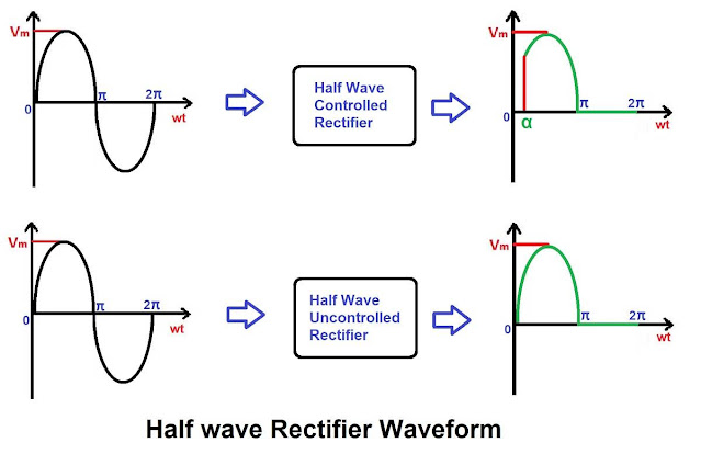
Half Wave Rectifier Waveforms
In summary of the above discussion on the operation of a half wave rectifier with controlled and uncontrolled switches, we can observe that the input and output waveforms for the half wave rectifier are depicted in the given figure.

Half Wave Rectifier Formulas
In this section of this
article, we will provide those formulas of half wave rectifier that are mostly
used. To understand detail derivation of these formulas and off-course more
formulas of half wave rectifier please visit Half Wave Rectifier all Formulas with Derivation
Average Value of Half Wave Rectifier
The formula for
calculating the average value of the sinusoidal waveform is

After applying this formula for both types of half wave rectifiers output wave then we will get the average value of half wave rectifier.

Above equations show the formula for calculating the average output voltage of a half wave rectifier. In these equations Vo is the average output voltage of half wave rectifier and α is the firing angle of SCR.
Half Wave Rectifier RMS Value
The formula for calculating the rms value of sinusoidal waveform is
In above equation Vor
represents the RMS Value of the output voltage and T represents the fundamental time period of the output waveform of the half wave rectifier.
After applying this formula for both types of half wave rectifiers output wave then we will get the rms value of half wave rectifier.

Form Factor of Half Wave Rectifier
Form Factor of half wave rectifier is defined as the ratio of RMS Value of half wave rectifier to Average Value of half wave rectifier i.e.

Ripple Factor of Half Wave Rectifier
Formula for calculating the ripple factor for half wave rectifier is

Efficiency of Half Wave Rectifier
Efficiency of a half wave rectifier is defined as the ratio of DC output power to the AC input power.

Advantages of Half Wave Rectifier
Among all the rectifier circuits the construction of half wave
rectifier circuits is simple and the cost of designing these circuits is less,
as they are using only one switch. This is only the advantage of half wave
rectifier circuit.
Disadvantages of Half Wave Rectifier
Despite the above discussed advantages, the half wave rectifier
circuit is often not preferred because it has certain disadvantages and these
disadvantages are more significant than its advantages. Some of the major
disadvantages are listed below.
- The main disadvantage of half wave rectifier is its efficiency, as its name defines “Half Wave Rectifier”, it converts only half waveform of the AC voltage into DC voltage and the rest half of the AC waveform is lost. Due to this power loss efficiency of the half wave rectifier is less as compared to full wave rectifier.
- Typically, the maximum efficiency of a half wave rectifier that is designed by using only diodes is 40.5%, if diodes used are ideal. Whereas, the efficiency of the full wave rectifier that is designed by using only diodes is 81%.
- The Ripple factor of half wave rectifiers is more as compared to full wave rectifiers. Means, the ripple content in the output waveform of half wave rectifiers is more as compared to full wave rectifiers. Therefore, the AC component in the DC output voltage is significantly more as compared to full wave rectifier which is not suitable for the applications requiring a steady DC voltage. Hence it is not practically used.
- To get the smoother waveform from the half wave rectifier more filtering is required because in the half wave rectifier output ripple content is more.


No comments:
Post a Comment
Please feel free to provide feedback and suggestions, and also don't hesitate to ask your questions.